Site Modeling in Context
Rhino Terrain Workflow
This is the beginning of a tutorial covering the basics of exchanging terrain data form ArcMap to Rhinoceros and developing a site model using the RhinoTerrain Plugin. This page discusses a workflow that begins with obtaining terrain and groundplan information from public sources, assimilating it using Geographic Information Systems and developing finely articulated design alternatives using RhinoTerrain.
New! Video Capture of this Tutorial
GIS to Rhino Terrain Thanks to Aidan Ackerman of the Boston Architectural College for funding to overhaul and update this tutorial, and for capturing this video!
References and Resources
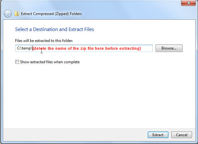
- The Demo Dataset For best results, extract the contents of this zip archive to c:\temp See Image
- Obtaining Terrain Models and Orthophotographs
- Georeferencing Scanned Maps
Compile and Explore the Data in ArcMap
There ae a couple of demo datasets to choose from in the list of resources, above. Or if you like, you can follow the instructions on Obtaining Elevation Data and Aerial Photography. We bring these together in a geographic information system that will reconcile the various coordinate systems used by these layers, and will allow us to explore large datasets to better understnd the context of our project.
- Extract the contents of the demo dataset zip archive to your c:\temp folder.
- Open the file docs/topo_modeling_demo.mxd in arcmap.
- If you feel like it, explore the different layers by turning them on and off and poking at them with the identify tool.
- Inspect the source properties of each of the layers. Note that many of them use different coordinate referencing systems
- Inspect the Coordinate System properties of the data frame (the ting that says Layers.
- Take a look at the ned_thitdsec_utm.img. This is an elevation model from the United States Geological Survey that we will use as the base model or our design. For more information about obtaining these raster elevation models. see Obtaining Digital Elevation Models
Create a Georegistration Frames and Groundplan Images
You will need three rectangles. One each for your context frame, design frame and surround frame. YOu will also want to have aerial photographs or other groundplan images that fit perfectly within the Context and Surround Frames. The process for creating these is discussed in the page, Creating Geo-Registration Frame and Groundplan Image
Create a Groundplan Images
The first step is create images of the existing condition and of your design that are clipped precisely to the design frame polygon. There are lots of ways of doing this. We will use ArcMap to export an image or a pdf of the aerial photo with the design frame on it. Then you can print this out and use it as a base photo for developing a design using colored pencils on trace. Then we will scan the design, and crop it in photoshop and put the result in your Manuscript/Groundplan_Images folder. It ia named, hargreaves_plan_design_frame. You can also see other images i the groundplans folder that we exported from ArcMap the same way. The key thing is that eaxh image is clipped exactly to one of the frames.
Export the Terrain Raster to an Ascii File
Take a look at our raster elevatiion model
The best way to get a GIS - based elevation model to Rhino Terrain is by exporting it to an AsciiGRID. This is accomplished with the Raster to Ascii tool in the Conversion Tools>From Raster toolbox, as described in the Digital Elevation Models tutorial. Note that we set the Processing Extent environment variable to match the extent of our context frame. So that the resulting ascii file matches perfectly with the edge of our context frame. You wil find this exporrted file in work/gis/schemes/ned_10m_context_gridascii.asc
Import and Arrange your Source Data in Rhinoceros
GIS is a great tool for bringing together diverse and large datasets, but at this stage in its evolution it is not as great a tool for 3d editing as Rhinoceros. The RhinoTerrain plugin bridges the gap between rhino and GIS. So our workflow now involves an exchange with Rhino.
Import your Frames and the Ascii Grid
If you are opening a new Rhino File, choose the template for Large Models in Meters. But for now, just use the Condor_St_wilds_master.3dm file provided in the folder manuscripts\cad.
Use rhinoterrain's Import. > ArcMap Shape File to import your frames. Easy. Importing the asciiGrid is accompished with the RhinoTerrain > Import > ArcInfo AsciiGrid tool. Before importing this ascii Grid it is a good idea to create a new layer called asciiGrid and make it the active layer in Rhino. Otherwise it will go on your default layer, and you will have to move it later. If Rhino does not recognize the ascii file that you made with arcmap, try changing the file-type pull down to recognize "all filetypes" -- not just hose with a .asc suffix. When prompted for a coordinate system, choose Use Input Data Coordinate System. At the next prompt, choose Import as Pointcloud.
Import your Surround Frame and Context Frame.
Scale the Model
Since some of our design documents reference elevation in feet, we will now use the Units command in rhino to scale the model to feet.
Create the Context Mesh
Our first mesh is made using the pointcloud that resulted from our import of the asciigrid. Select this pointcloud object and choose Rhinoterrain > Mesh > Create Terrain Mesh. This command is fairly straightforward. You have to make sure to choose the Accept option to finish it off. For fun,switch your perspective window to Render Mode. TO keep things neat, you should move this new mesh to a layer named Context Mesh
Drape the Context Orthophoto
The terrani model is cool but lacks important details. For a better idea of what is happening, we can drape the orthophoto that e exported frm ArcMap. Use the RhinoTerrain > Imagery > Orthophoto Map on DTM command. When prompted for amesh, choose your mesh. Then select our work.groundplans/context_ortho_bathymetry.jpg. YOu should now see a colorized orthophoto with batheymetry from the NOAA navigational chart draped on your terrain mesh.
Begin Articulating your Surround Model
Now that we have set up our context model in rhino, we are ready to cut out the area of the model that we are going to articulate for our surround and design models.
Create a 3d Surround Frame
Our model is going to have three pieces. a context, which we are going to leave exactly as it cames ot us from the USGS. We will also have a Design model within which we may modify the terrain however we want. In between the design and the context, we need a Surround model that mediates the inner model to the outer model.
The first thing we will do to our surround model is create a 3D frame that wil lserve as the match line between the surround and the context. Before cutting out the middle of the surround model we wil fix it by adding details about the river shore line and high and low tide from our NOAA Navigational chart.
The 3d surround frame provides a match-line that defines where the surround model leaves off and the context model starts. This line will become an important part of the surround model. We will make this new feature using the Rhino Project function. We want to preserve our flat surround frame, so turn Delete Input off. Lets start a new group layer for our surrond model and with in this make a layer for the 3d surround frame, and move your new object to this.
Create a Reference Image
We use the PictureFrame command to import a reference image that we can use in plan as a guide for improving our surround model. We wil use the Context_Ortho_Bathymetry.jpg as the bitmap image and will use the Context Frame to register it.
The good thing about the picture-frame tool as opposed to BackgroundBitmap is that you can have several pictureframes in your model and you can use layers to keep them organized. You will need to move your pictureframes down below the lowest elevation in your model (about 40 feet below seal level.)
Use reference images in TOP view only, since perpective view will give you parallax errors as you ae looking through your wireframe at a spot in your image that is not directly underneath.
Clip Out the Source Surround Mesh
Our source terrain model is rough. It is good enough for context, but for the area surrounding our design we need to fix it up a little. We will use the rough mesh as a start, so we will create a surround mesh using the MeshSplit function applied to the context mesh -- using our surround frame as the splitting object. This works best if you are in top view. We will move the new surround mesh to a new layer in our surround model group layer.
Create Contours for the Surround Model
We need our surround model to provide a context that is logically consistent with our design model and with the context model. In the case of our condor street project, you will notice that that our design frame has some streets and sidewalks that connect with the outside world. There is also a baseball field accross the street with an earthen grandstand that we want to look right. We also want to model the river channel in the surrounding area so that we can roughly represent this in our models. So in order to make all of this work we need some handles with which we can grab the terrain surface and move it around. We don't want to have to adjust every point in the mesh. What we will do is convert the surround mesh to contours.
Contours are a nice familiar way of visualizing terrain, yet they aren't the most concise way of controlling it, as shown in the Terrain Modeling in Context Page. If you choose a contour interval that is fine enough to express the fine details in a landscape, you wil also get a great deal of geometry that does not actually express anything important. This is fine if we are just visualizing, but if you want a nice concise model for editing , too many contours can put you in a similar situation of having to manipulate every point in a pointcloud. Pruning a set of contours to define the critical places in the landscape where the terrain shifts is a large part of the art in developing malleable, expressive terrain models!!
In the case of our demonstration site, some of the critical elevations we have to consider are related to the high and low tides. To get a notion of what these are, we will consult the NOAA navigation Chart. We also want to know more precisely what the elevations are for the top of the seawall and the sidewalks and streets that cross into our design frame. For the latter, we will consult our LIDAR data. After playing around with the RhinoTerrain > Create Contours From Terrain tool, I have decided to make contours at an interval of 3 feet with an index contour every 9. This interval seems to capture the essential elevations in the surround without too much extra.
Convert Contour Polyines to 2nd Degree Curves
The contours that RhinoTerrain creates are polylines. These are awkward because to manipulate these we would have to attend to each vertex. Luckily we can use the Rhino FitCrv command to convert these to easily manipulated NURBS curves. I choose to use 2nd degree curves because these have one control point for each arc which should allow us to express the sorts of curves that we need. We can adjust the amount that the contours are simplified by adjusting the Fit Tolerance. After fiddling with this I have chosen a fit tolerance of 2 feet. Use PointsOn to take a look at your new control points. We put the new contour curves onto a new layer which will become our Manuscript Layer for contours. The term Manuscript indicates that this is a layer that we will modify.
Annotate Contours
Select your contour curves and use RhinoTerrain > Annotate Contour Curves to add labels to your contours. The size of the annotation can be set using Tools > Options > Dimensions. Once a Dimension style has been created it can be selected in the options for the Rhinoterrain command -- but only if you do not select the contours prior to running the command!
Adjust Contours and Add 3D Breaklines
Editing contours is best done in plan view, with the Planar Snaps turned on.
We are going to start by fixing our terrain model based on details we can see in the NOAA Navigational chart. Most importantly we can see the low tide line at approximately 0 feet, high tide at about 9 feet. The edge of the channel is at approximately -3 feet and the bottom of the channel is at around -36 feet.
We start by eliminating the existing 0, 3 and 9 foot contours with the Trim command. Trim these using a couple of lines just inside the east and west edges of the Surround frame. We leave stubs of these contours inside the frame because we want to make sure that we dont alter the way that these contours meet with the Context mesh. With the Trim command, you want to set Apparent Intersections to Yes..
Now I use the Curve Command to create new contours, starting with zero. Remember not to touch the Surround Frame. In fact, the zero contour and under water contours will close inside the frame to create a nice neet depression for the river channel inside the surround frame.
We are going to make our contour with the Curve tool with Degree set to 1. When we are finished we adjust the height of each contour with the SetPt command.
The elevation of control points on 3d curves can be adjusted by selecting one or more control points and using the SetPt command. You want to uncheck setX and Sety so that you are only changing the Z coordinate. The new elevations are set using world coordinates for example, typing w0,0,16 at the command prompt. While this adjustment can be made in plan mode, it is a good idea to check the shape of the 3d breakline curves by tilting in perspective.
At the front of the seawall, I have created another line that I designate as a Hard Breakline that specifies that my surface will have a crisp break in grade at this line. I measured the elevation of this seawall from the LIDAR data in GIS. It is 3 meters or approximately 10 feet.Hard 3d breaklines are placed on their own layer because we wil need to discriminate layer when we rebuild our mesh. From here on out we will consider our planar countour lines as soft breaklines.
It is important to keep your Hard Breaklines on a separate layer so that they can be independently selected when you make your mesh. I also keep planar breaklines (contours) on a separate layer so that they can be colored differently and selected for annotating with the RhinoTerrain contour annotation tool.
Creating Terrain Meshes
Create a Mesh From NURBS Curves
Once you have got the contours adjusted the way that you want them, you can create a mesh directly from the curves. YOu can do this with the Rhinoterrain > Mesh > Create Terrain Mesh tool. To do this we will select all of the contours and breaklines and the 3D Surround Frame. Then when the tool has been invoked, we will choose the Hard Breaklines option and choose our hard breakline. Then we will choose Complete to finish the mesh.
Apply Plan Images to Terrain Model
Your terrain surface is rather plain looking. Wouldn't it be more informative if it showed the difference between aspects of the site, like tha raeas coverd by water, roads, houses and vegetation? You can have it all!- Select your terrain mesh and look at its Object Properties.
- I nthe Materials properties, set the Texture color by choosing one of the Surround images form our work/groundplan_images folder.
- In the Texture properties, choose Apply Planar Mapping.
- Rhino asks you to pick the corners off the bounding rectangle. This works best in Top view and with the Surround Frame visible and unlocked.
- Then Rhyno asks if you are chosing a UV Mapping or UVW. Choose UV.
- Now use the UV Editor in the Texture panel, and click the bounding corners again.
- Back in the texture controls, choose Apply to apply the UV transformation.
- Now with the Mesh stil lselected, choose Explode
Now that you have been through all of this, you should have enough skills to clip out the mesh within the design frame, load the design groundplan as a picture frame and start spinnning out alternatives for your park!
Create your Design0 Model
Our Surround model now also contains a model of the initial condition for our Design Site. What we will do next is repeat the same procedures that we used to clip out our surround mesh frm the context model. Before we begin this we create a new group layer to hold all of the controls that will be used to generate new variations of our design model.
- Create a 3D Design Frame by projecting a copy the Design Frame onto the Surround Mesh.
- Use MeshClip to clip out the design0 mesh from the surround mesh.
- Make new layers for our contour curves, copy the surround curves into these layers and then trim them using the Design Frame.
- Copy the masspoints.
The controls that make up this design model can now be copies to create any number of alternative models. As long as these models all respect the geometry of the 3d Design Frame, they will nest seamlessly inside the Surround model.
Each Design Alternative can have its own PictureFrame
Now to begin creatnig our first design alternative, we will use the pencil drawing created by Kaki Martin and Mark Klopfer when they worked for Hargreaves and Associates. Note that we have to push the pictureframe down ro -30 feet so that it stays below the deeper parts of our model. ALso remember that the Pictureframe should only to be used as a guide when you are in Top View.
