Site Modeling in Context
Creating a Geo-Registration Frame and Groundplan Image
This tutorial is part of the sequence of tutorials oncerned with workflows for Site Modeling in Context. A big idea in these workflows is that a site model should relate to its geographic context in terms of the circulation and other aspects of groundplan and the terrain. If there are abrupt discontinuities between the site ad the context, these should serve the design, and not merely be an inconvenient accident that comes to us simply because of lack of adequate tools or information resources! The desire to have a site model that relates to its context leads us to definitions.
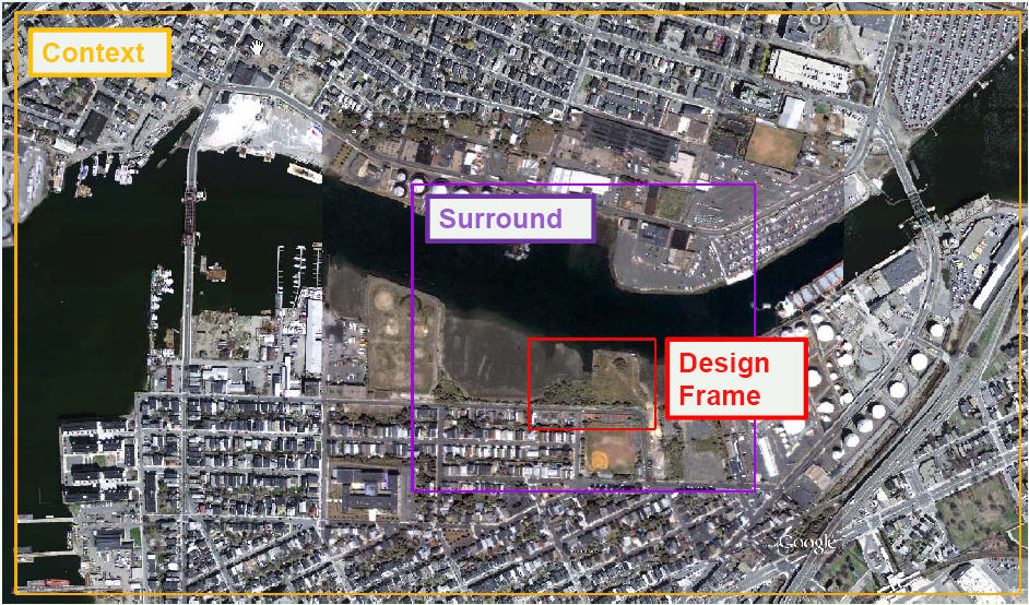
There are three parts of a site model:
- The Context Frame: The context of our site includes that area of the landscape where we are concerned about views into the site and views out of site. This area may be quitre large. Within this frame we are likely to have a rough terrian model and a source of planimetric groundplan information, at least an aerial photgraph that we can pull from the information infrastructure provided by government agencies.
- The Design Frame: The area that is limited to the area within which we can make changes in terrain and groundplan. WIthin this area we would like to have a model that represents the existing terrain and groundplan condition that we can consider a point of departure. This model will serve as the starting place for any number of alternative site models.
- The Surround Frame covers the area that lies outside of the design frame, and is limited to that area that we need to make logically consistent with our site design. The terrain and groundplan data that we might obtain from sources may not have the precision that we need or may not be current enough to provide the setting that is logically consistent with the "Existing Condition" that we consider our design setting. The surround model is that area that reqires fixing to make sure our design model plugs seamlessly into its context. At its outer edge, the surround model matches in 3D with the context model. On its inner edge, the surround model matches in 3D and in Plan with the Design model.
A large part of the value in specifying these frames is that it is helpful to be clear from the start of the modeling project what the spatial limits of our model need to be, and the precision of data that we need for the different parts of the model. Getting this straight at the begingng helps to avoid very time-consuming effort being spent adding detail to our model that are irrelevant, or worse, needing to extend the model after we have made investments in one set of assumptions.
Interoperability and Geo-Registration
One thread trough the workflows for site modeling in context is that we will use many tools to deal with data compilation, terrain modeling, and developing a vision for the site groundplan and programming mong other things. Our agility in developing coerent ideas while using a diverse set of tools reqires interoperability, or the ability to pass information from one tool to another in a flent way. Our frames will be very helpful in this regard. The key to holding all of the parts of our model together is the three dimensional spatial referencing system. Whether we are taking our source data from GIS or Google Earth, we have this frame at the beginning, but as we pass the terrain and groundplan information to Rhinoceros, or Adobe Illustrator or Photoshop, the fre a ames will provide a means of precisely registering the parts of the model that we work with an all of these different programs, whether they be vector or raster based.
Some aspects of our modeling workflow involve the transfer of planimetric infomaion about groundplan as raster images. These images can wuiclkly be draped on terrian surfaces as means of checking and presenting the logical relatiinships between the terrain surface and the groundplan. Because raster images are always rectangular -- even if they have a transparent area around the outside -- it is important that our model frames are also rectangular -- and that the coorcinate referencing system that we use has the properties of orthagonal north-south and east-west axes. The best choice for a spatial referencing system will be the apropriate zonr of the Universal Transverse Mercator projection system, projected on the model of the earth provided by the World Geodetic Spheroid of 1984. This is the coordinate framework used by Google Earhth and Google Sketchup. Click the following for more information on Geographic Referencing Systems and a handy map of UTM Zones. By using a UTM coordinate system on WGS 84 we know that a rectangle we make in ArcGIS will remain a perfect rectangle in Google Earth and Sketchup and this will save us a lot of headaches later on.
Creating Clipping Polygons and Reference Images
The important thing about model frames is that they should be georeferenced, rectangular polygons that we can use to clip and register vector and raster data in a predictable way. THere are many ways to do this using Google Earth or AUtoCAD, Rhino or Adobe Illustrator. The workflow described here begins with ArcGIS. As a Geograpic information systems ArcGIS has advantages over all of the tools discussed above in terms of its capacity to bring together data sources that may originate in any number of geofraphic coordinate statems, and to export data in DWG format files used by CAD programs, KML that is used by Google Earth, and Sketchup files. Currently we at the GSD are using both ArcMap 9.3.1 and ArcMap 10.0 . The latter has many bugs including the unfortunate one that makes the Export to CAD tool very unpredictable. Nevertheless arcMap 10.0 can make shape files, and these can be imported into RhinoTerrain. The basic steps for creating clipping frames in ArcGIS 10.0 and 9.x are provided below.
Regardless of wich tool you ae using, the first step would be to think about the extent of three frames. It is useful to do this with an aerial photo and terrain model in front of you. Obtaining these is explained in the tutorial Gathering Digital Elevation Models and Aerial Photos from The INternet. YOu can also get a decent overlay of world-wide aerial imagery in arcmap b shoosing File>Get Data form ArcGIS On-Line. References for other imagery that may be useful are compiled on the web page Sources of Geographic Images. Any image, including the groundplan images of your design originating from your imagination, can be brought into registration with the GIS coordinate systems using the techniques described in Georeferencing Images
The first goal is to create three clipping frame polygons. We will assume that each of these will be a separate shape file. The next goal is to export images that have these polygons burnt into them.
Create a Clipping Frame in ArcMap 10
- Arrange your data in arcmap to create a basemap that you want to use in other applications.
- Adjust the Data Frame properties to choose an apropriate coordinate system. I recommend the local zone of the Universal Transverse Mercator projection scheme, using the World Geodetic Sphereoid of 1984 (WGS 84). Boston is in Zone 19N.
- Use the Rectangle tool on ArcMap's Draw Toolbar to create a rectangle that will seve as your frame.
- Right-Click the Dataframe and choose Convert Graphics to Features. When saving, be sure to set Save Files of Type to Shapefile.
Exporting an Image from ArcMap with the Clipping Frame
As we have explained abve, one element of our site model will be an image of the groundplan for our site and its context. These images will be clipped to our context frame and surround frame, and this will make it very easy to register them with the terrain meshes that we make in whatever program we are using to do that. So whil we have ArcMap open with an aerial photo, we will go ahead and dump out high-resolution images with our clipping xtents burtn into them. Lucklily this pocedure is the same in both versions of ArcMap.
Before we get into exporting the images we should think about resolution. We don't want the images to have more resolution than we need, because this will create unnecessary problems in every ting we do subseqently. Nore do we want to export the images with more resolution than is in the originals, because this is just silly.
- Zoom in on your image until you can see a pixel. Use the Measure tool from the Tools toolbar (looks like a little ruler) to measure the pixel in meters.
- Zoom out to your context frame and measure its width in meters.
- Fo rthe context image, you don;t necessarily ned a very high-resolution image. A good resolution for your context image may be about one meter per pixel, which is good enough to see distinquich buildings, roads, cars, etc.
- Thinking about it another way, many programs like AutoCAD and Sketchup will choke if you try to drape a texture with more than, say 4000 x 3000 pixels... So if your context image is more than 4 kilometers wide, think about that.
- Arrage your map display to include the frame that you want to use to clip the image. You may also want to use other overlays with transparency to colorize the photgraph or to include details formsome other GIS layer that you have.
- Choose File>Export Map to export a jpeg image. You can use the options for the export jpg dialog to set the quality to about 95% which will substantially shrink the file size.
- Repeat these steps for your Surround frame. You want to make this image a substantially higher resolution. TOu could go down to 30 centimeters per pixel if your sourc image has this kind of detail.
- Now you can go into photoshop and crop these images to their frames. I like to split tha actual frame border.
- If you plan to use these images for thre dimensional visualizations in ArcGlobe, you will need to Georeference it. Even if you saved a world file when you exported the raster, this will become invalid once you clip it. Thankfully it is very easy to georeferenc your raster since it is clipped exactly to your frame!
