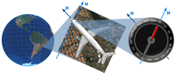
Flying over Campinas, Brazil, an airplane reads its heading H as the angle from the local meridian M, i.e., the north-south line pointed to by the compass's needle (once compensated for magnetic declination): here it is 292.5°, also known as west-northwest. In the absence of crosswinds, the heading coincides with the direction of travel, or bearing.
Whenever one plans moving from a point on Earth to another far enough to be out of sight, or on the sea or above the clouds where no paths are marked, some very related questions arise:
Directions on a surface are stated as a bearing, i.e., the angle from a reference line. On Earth, this line is the meridian through the current location, and the bearing is usually measured in degrees, from 0° northwards and increasing clockwise to 360° northwards again — on Earth this angle is more commonly known as the azimuth. The direction of the current meridian can be obtained from an ordinary compass, whose needle is always aligned with the magnetic north-south direction, but one must account for magnetic declination, the deviation of magnetic north from true geographic north. Magnetic declination is not uniform throughout the world and slowly changes with time (in millions of years, the magnetic "poles" have even switched hemispheres several times), therefore nautical charts must be periodically updated with reference correction marks for declination. Gyrocompasses and astrocompasses are immune to magnetic declination; on the other hand, a gyrocompass depends on a power supply to keep its wheel spinning, while operating an astrocompass requires a precise clock and up-to-date astronomical tables.
A loxodrome with bearing 292.5° passing through Campinas, Brazil, as represented on an oblique semitransparent azimuthal orthographic map and on a polar azimuthal stereographic map with two hemispheres.
Changing the bearing to 275° makes for a longer path, but the endpoints are the same. Notice how Hawaii's southern skirts can still be reached after an extra turn around the world.
If its angle remains unchanged from every current meridian, a path is a loxodrome or rhumb line, a line of constant bearing. The concept was, perhaps after suggestions by Martim Afonso de Sousa, invented by the Portuguese scholar Pedro Nunes (or Nuñez) ca. 1533, although the precise mathematical details were understood only much later.
A parallel crosses all meridians at straight angles, thus all parallels are closed loxodromes in the east-west direction. All meridians are obviously trivial loxodromes in the north-south direction. For all other directions the loxodrome is an open (i.e., with two distinct ends) three-dimensional curve known as a spherical helix or loxodromic spiral: each end reaches a pole after an infinite number of tighter and tighter turns.
Two points not on the same parallel or meridian can be connected by an infinite number of loxodromes, but one is almost always interested on the shortest, "steeper" one, which crosses less than half of the meridians; the other rhumb lines do one or more additional turns around the Earth.

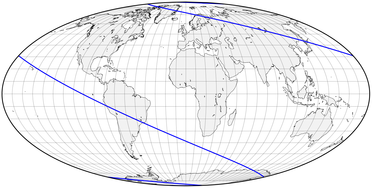
The loxodrome for the 292.5° bearing, as shown in an equatorial map using Mollweide's equal-area projection. The spirals near each pole are too close to the map's border to be seen.
The same rhumb line in an equatorial equidistant cylindrical map. Again, the curve turns around the world several times from pole to pole. Compare the constant parallel spacing on this map with the stretching of Mercator's projection below, which straightens the loxodrome out.
Clearly rhumb lines are not in general the most direct route to either pole. In fact, the Equator and the meridians alone are not only loxodromes but also great circles, containing the geodesic lines which are the shortest path between two points. On the other hand, in the absence of reference points the loxodrome is the easiest path to follow: once the proper bearing is established, it is enough keeping it true — i.e., the compass's needle straight aligned — to be sure to reach the destination. Reality is a bit more complicated for aquatic and aerial vehicles: crosswinds, waves and streams cause the bearing to deviate from the heading, unless compensated.
How do projections determine how the loxodrome is drawn on flat maps? The azimuthal orthographic projection clearly shows the spherical helix's shape, but it is useless for measuring bearings, unless the starting point lies at the center of projection. On the polar aspect of an azimuthal stereographic map, the loxodrome appears as a logarithmic spiral; this is a direct consequence of this projection's conformality: the logarithmic spiral is a plane curve which intersects all of its radii at the same angle; it is also self-similar, looking the same no matter how magnified.
The same loxodrome in an equatorial Mercator map appears as a series of parallel straight lines. This barber-pole pattern would continue to infinity above and below had not the map been arbitrarily clipped between 85°N and 85°S; most Mercator maps have much narrower latitude ranges.
A transverse Mercator map can present the poles but, conversely, must be clipped far from the central meridian. Exactly the same loxodrome retains its angle with each meridian; however, since the graticule is curved, the map is not appropriate for directly evaluating directions.
Most other projections are poorly suited for presenting or calculating loxodromes, which are mapped to complex curves. The exception is Gerhardus Mercator's most famous conformal projection: in the equatorial aspect all meridians are vertical lines, and all loxodromes are straight lines. Consequently, in order to determine the bearing between two points it is enough connecting them on an equatorial Mercator map and measuring its angle, or slope, from the vertical: a straightedge and a protractor are sufficient.
How does Mercator's design compare with another common cylindrical projection, the equidistant cylindrical? In the latter, parallels are equally spaced and the loxodrome is curved towards the Equator. Mercator progressively spaced apart the parallels, in proportion to the trigonometric secant of the latitude; the exact mathematics was not available at the time, so Mercator probably resorted to geometric approximations. Unfortunately, since the secant is infinite at the poles, these lie at infinity and cannot be included in real maps: to do so while keeping correct angles would join meridians at two points, which is impossible in a cylindrical map.
Two loximuthal maps, with the central meridian intersecting the reference parallel near Campinas (top) and Tromsø, Norway (right). The same 292.5° loxodrome touches those two locations, but is straight only in sections passing through the intersection point, with uniform scale evidenced by the red circles, spaced 10° apart.
In fact, parallel spacing is so exaggerated at higher latitudes that equatorial Mercator maps are often clipped about 70-80° north and south. This is not too relevant for navigation (near the polar caps, magnetic declination is too significant anyway, so in these comparatively small areas other tools are employed), and Mercator's projection has faithfully served route planners for centuries.
Another noteworthy projection, the loximuthal, devised independently by K.Siemon and W.Tobler, shows all loxodromes intersecting at a special point on the central meridian as straight lines with constant scale and direction. Unfortunately, like the azimuthal equidistant and unlike the universal equatorial Mercator, loximuthal maps must be tailor-made for each point of interest.